Materials
$65-100 Inexpensive fiber channel adapter (QLA21001). Merchant: eBay
$15-40/per fiber channel drive (I used the Seagate ST39102FC, but it's a bit old, so I'd look for other options. Check Seagate's website for drive specifications.). Merchant: eBay or www.sanfordnsons.com.
$39 HSSDC cable (HSSDC/DB9 cable, Adaptec, MFG. Part #: 1879500). Merchant: Provantage.com
$2.01/per AMP 557101-5 connector on www.hawkusa.com. ($25 dollar minimum order. For smaller quantities, see sites listed on www.amp.com for the 557101-5 (click the pricing button).
$1.50/per molex connector. Merchant: www.caseetc.com (I bought the 90 degree connectors, but, by chance, got a few of the straight connectors shown in the pictures--which is good, because those were the type I was looking for in the first place.)
~$50 Radio Shack/Fry's/Any other electronics store stuff: 15 watt soldering iron, breadboard (.100 x .100 spacing" .042" hole diameter), Cat 5 Ethernet wire, an extra soldering iron tip (optional, but useful for beginners), male & female serial connectors (DB9), soldering jumper wire, 1-Megohm resistors (1/4 watt, 5% tolerance). When buying solder, get the thinnest electrical 'rosin flux core' solder you can, since it is much easier to work with than the thicker types.
So, a two drive system would probably cost you about $160, minimum, while an 8 drive system would most likely set you back at least $320 (these are just rough estimates).
Construction
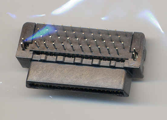
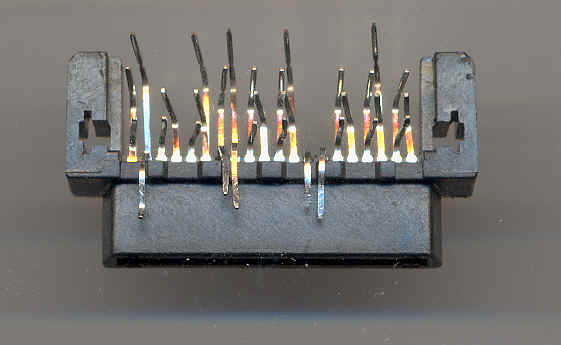
Step 1: Take your AMP connector, turn it upside-down, remove the little black board-thingy around the pins. Also, push the clip-like pieces of metal on the sides up and out. Align the pins as you see below.
Ā
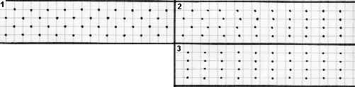
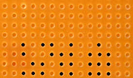
Step 2: This can be done before alignment, but you need to get rid of some pins (bend them up or down, or simply pull them out.) In any case, you won’t need them in the future. This diagram of the bottom of a breadboard with the connector put in place shows which pins to keep (the black dots). Connector plug is oriented down.
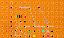
Step 3: The red dots in this diagram show where the resistor wires come through the bottom, and the colored stripes (gold-green-black-brown) show which direction the resistor should be pointing (I’m not sure if it matters at all, but I know it works this way.). The blue dots are where the molex connector pins come through the bottom. In those places, you will need to widen the breadboard holes a bit.
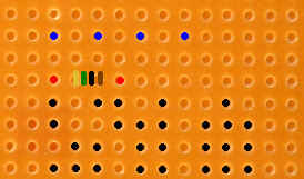
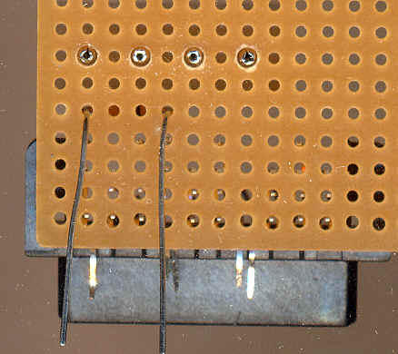
Step 4: This diagram shows how all the pins should be connected. I used Radio Shack soldering jumper wire for this and it works, but other types (paperclip?) might be fine as well. This wiring simply carries power to the drive, so it probably doesn't need to be copper-cored.
Instructions on how to solder are on the box that comes with the soldering iron, and remember that although it is a pain to heat the joint, and not the solder itself, it is going to be easier in the long run because you will be using less solder, and less is good in tight spaces. But don’t worry if you end up making tall solder sculptures on the joints of your first card, since you will get better with practice.
Also glue the molex and AMP connectors down first with some good glue (superglue does not work, in my experience).
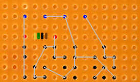
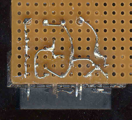
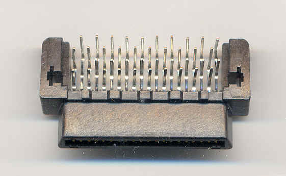
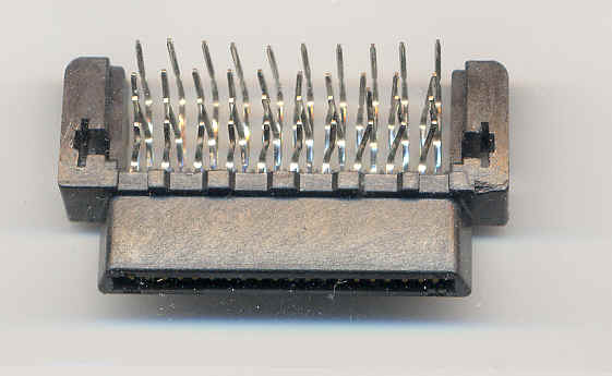
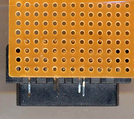
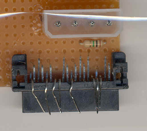
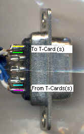
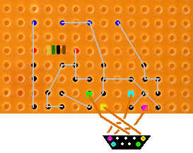
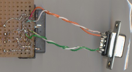
Step 5: Look at the color-coding on the serial connector and the T-Card. You need to put a length of Cat 5 wire or soldering jumper wire2 between like colors (blue to blue, purple to purple, etc.). See the third image for the theoretical final result (BTW, the wires don't need to be crossed, it's just that I found it easier to represent the DB9's with the wider part up.)ĀThe last image shows a completed T-Card (note that the bottom [narrower] side of the serial connector is now facing you.). The appropriate colors are traced faintly onto the image to make the location of the wires a bit clearer.
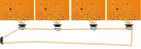
Step 6: If you want to put these into a loop (fiber channel supports up to 126 devices on a single loop), just put a the T-cards into a series, as shown below. You may use Cat 5 ethernet wire, or even longer lengths of soldering jumper wire for the loop wiring.Ā The connectors with the black faces are female (no pins) and the ones with the while faces are male (pins).
In the diagram, the back of the female connector has been made 'transparent' so you can see how the pins & holes match up. The advantage of mating the T-Cards to the loop with serial connectors is that you can remove the drives (just pulling out the T-Card from the drive will no suffice) and put a pass-through connector, that simply connects the purple to the yellow and the blue to the bright green.
Step 7: You now have anywhere from one to 126 connectors. Next, you want to punch out a serial port in the back of your computer (or buy/cannibalize a serial slot faceplate), and stick the female connector on the far right into the hole so that the connector faces out. Then, connect it to your HSSDC cable, and lead the end of that to your QLA2100. Other adapters might accept the serial cable itself, instead.
Step 8: So, you have all your drives mounted, T-Cards connected, the power is hooked up, and the serial cables are going where they need to go; fire the thing up!3 If you are using the QLA2100, it should be automatically recognized, and the QLA should stick in its little BIOS sequence after the main computer one.
To get into the QLA BIOS screen, press Alt-Q. In there, you can make sure that your drives have been recognized, you can low-level format them, or even do some rudimentary testing. There are plenty of settings to play around with, but I won't cover those, since they're all in the manual.
If you are running Windows 2000, the card should be automatically recognized, and all you might want to do is update the drivers and perhaps download some of the QLA utilities (they are by no means essential).
If you want to set up a RAID, go into Windows 2000's Computer Management and then Disk Management, and create a volume over the drives; it can be striped, plain, mirrored, or even RAID 5. Unfortunately, those of you without Windows 2000 (or Linux) are pretty much out of luck as far as RAID goes, but perhaps there are some standalone software RAID packages.
Of course, even without one, you can still take advantage of the cheap and relatively fast storage space.
Well, that's pretty much it!
----------------------------------------------------------------------------------------
1 The QLA2100 has 100MB/s throughput, the next model up, the QLA2200 has 200MB/s throughput in full duplex mode, and the QLA2300 has 400MB/s full duplex throughput. I am not sure what changes have to be made to the T-card hardware to enable full duplex, but if anyone knows, I'm all ears! For now, though, I'd stick with the QLA2100. Anyway, 100MB/s isn't bad compared to IDE, since the ATA100's 100MB/s is the maximum *burst* speed, while I believe the 100MB/s (in the case of fiber channel) is the *sustained* maximum.
2 As long as it's copper cored, since this is, after all, copper-based fiber channel. Incidentally, if you wish, you may look into the possibility of converting the copper signals to optical signals, and back again, over the length from the T-card output to the HSSDC; thus, you would be able to run your drives quite a distance from your computer. You'd bet totally on your own with this, though, since I haven't looked into it at all.
3 If you are making a loop, always first test the T-cards individually. If the connected drive is not recognized, go over your work and make sure that everything is soldered together properly and you haven't shorted anything out.
Note: This is not a project for someone who doesn't want to take risks, can't do things on their own, or simply doesn't have time and patience. You will need to solder, desolder, and solder again, just to get some things right. I hope this guide will be helpful, but by no means should it be treated as a totally definitive resource.